Lesson 5 understanding and working with parallel rc circuits – Embarking on lesson 5, we delve into the intricacies of parallel RC circuits, exploring their fundamental principles, practical applications, and the intricacies of circuit design. Join us as we unravel the complexities of these circuits, empowering you with a comprehensive understanding and the ability to harness their capabilities.
Parallel RC circuits, ubiquitous in electronics, play a pivotal role in shaping signals, filtering noise, and controlling timing functions. Understanding their behavior is essential for mastering the art of circuit design and unlocking their full potential.
2. Circuit Analysis

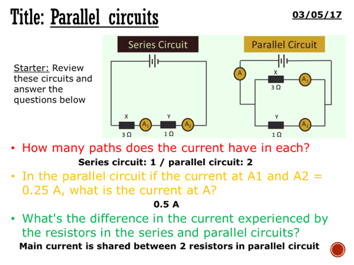
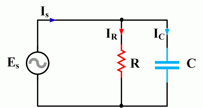
In parallel RC circuits, the voltage across each component is the same, while the current through each component is different. The impedance of a parallel RC circuit is given by:
$$Z = \frac1\sqrtG^2 + B^2$$
where G is the conductance and B is the susceptance. The phase angle is given by:
$$\phi = \arctan\left(\fracBG\right)$$
The time constant of a parallel RC circuit is given by:
$$\tau = RC$$
Resonance occurs in a parallel RC circuit when the inductive reactance equals the capacitive reactance. At resonance, the impedance of the circuit is at a minimum and the current is at a maximum.
3. Circuit Design
Parallel RC circuits are designed for a variety of applications, including filtering, timing, and oscillation. When designing a parallel RC circuit, it is important to select the appropriate components based on the desired circuit parameters.
- For filtering applications, the resistor and capacitor values are chosen to provide the desired cutoff frequency.
- For timing applications, the resistor and capacitor values are chosen to provide the desired time constant.
- For oscillation applications, the resistor and capacitor values are chosen to provide the desired frequency and amplitude of oscillation.
4. Simulation and Measurement

Parallel RC circuits can be simulated using circuit simulation software. This allows the designer to verify the circuit’s performance before building it. Once the circuit is built, it can be measured using oscilloscopes and other test equipment to verify its performance.
If the circuit does not perform as expected, it may be necessary to troubleshoot and debug the circuit. This can be done by checking the component values, the circuit connections, and the power supply.
5. Applications

Parallel RC circuits are used in a variety of electronic devices, including filters, timing circuits, and oscillators. Filters are used to remove unwanted frequencies from a signal. Timing circuits are used to generate pulses or delays. Oscillators are used to generate sinusoidal or square waves.
Parallel RC circuits are also used in power supplies to filter out noise and ripple. They are also used in audio amplifiers to provide equalization and tone control.
Essential Questionnaire: Lesson 5 Understanding And Working With Parallel Rc Circuits
What is the purpose of a parallel RC circuit?
Parallel RC circuits are used to filter signals, smooth voltage waveforms, and control timing functions.
How do you calculate the impedance of a parallel RC circuit?
The impedance of a parallel RC circuit is calculated using the formula: Z = (R – Xc) / sqrt(R^2 + Xc^2), where R is the resistance and Xc is the capacitive reactance.
What is resonance in a parallel RC circuit?
Resonance in a parallel RC circuit occurs when the inductive reactance and capacitive reactance are equal, resulting in maximum current flow and a phase angle of 0 degrees.